Image Registration
The DIFF_CALC module of TORTOISE is intended for image distortion correction, using image registration techniques. The details on using this software are outlined in the DIFF_PREP Software Guide.
To run the software, start the software as described in the Starting DIFF_PREP and DIFF_CALC section. This will open a GUI which has two panels. The panel on the left is used for importing the data. The panel on the right contains both required and optional fields for running the image distortion correction routines. The most important field will be the registration settings file. This is a pseudo xml file (with extension .dmc) which contains all of the various settings for running the software. The user can have multiple registration settings files. All of these will be stored in the DIFF_PREP_WORK directory.
Details for running the software and the registration settings file are described in the links below:
- running DIFF_PREP: Running DIFF_PREP with GUI
- registration settings files: 3.2 Registration settings
Post Registration QC check
It is important to check the quality of the eddy and motion correction and the susceptibility induced EPI distortion correction.
Eddy and Motion Correction QC
- load the _DMC.list file in DIFF_CALC
- click on display raw images
- select a slice in the middle of the brain, where you can see some major white matter structures.
- click on B_VALUES and scroll through all measurements for the same slice. Make sure the brain appears stationary in your screen. There should be no apparent motion of the brain in the FOV, and no stretching effects due to eddy distortions.
- click on SLICES and go to a slice high in the brain. Click on B_VALUES and scroll through all measurements for that slice, again, looking for apparent motion and distortion in the images. At the top of the brain it is often easier to see the effects of eddy distortion.
- click on SLICES and go to a slice low in the brain where the brain stem is visible. Click on B_VALUES and scroll through all measurements for this slice. At this level, it is often easier to see residual motion.
- The following 2 movies show an uncorrected dataset with some motion and eddy distortion visible in the left-right direction (due to the phase encoding direction being LR). The second is the same dataset corrected. Note that the motion and eddy distortions are no longer present. The apparent size difference of the two images is due to the resampling of the final output data to 1.5mm isotropic from the original 1x1x2mm resolution.
B0 susceptibility induced EPI distortion QC
The BSpline algorithm has some inherent instability, and can sometimes be affected by bright signal in the soft tissue, or other factors. For this reason, we STRONGLY RECOMMEND that the following QC steps are taken to check that no unwanted warping has occurred in the brain.
- With your favorite image viewing and ROI drawing software (we generally use mipav), load the following 3 images:
- _rpdtemplate.nii → this is the original distorted b0 image located in the _proc directory.
- _rpdstructural.nii → this is the T2 structural target image provided by the user, which has been co-registered into the native space of the DWI images, and so should be in the same space as _rpdtemplate.nii. It is also located in the _proc directory.
- template.nii → this is the b0 image after correction, located in _deformation_field directory inside the _proc directory.
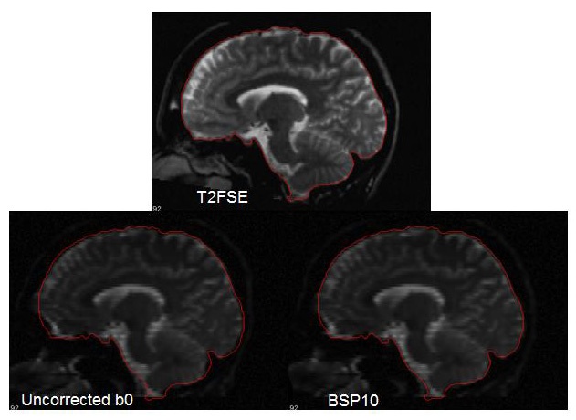
This figure shows some of the possible instabilities in the brain stem area. Likely, soft tissue was the driving force in the registration at this location, resulting in a stretch of the brain stem. If this occurs, you can re-run the software and adjust the bspline grid size. The bad correction here was achieved with a bspline grid size of 7, and the good correction was achieved with a bspline grid size of 10.

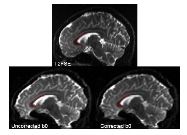
Sometimes the differences are not quite as obvious as in the above figure. So it is a good idea to draw some ROIs on both the whole brain, and several brain structures, such as the corpus callosum and the brain stem, to double check that the correction is good. To do this, define the ROIs on the structural target image (_rpdstructural.nii) and then copy them to _rpdtemplate.nii and template.nii. The ROIs should match well on template.nii and _rpdstructural.nii. You may be amazed at the amount of correction visible in the genu of the corpus callosum!

As in the above figure, it is also useful to rotate your images to the sagittal or coronal planes to view the correction. Another good correction is shown below in the sagittal plane, showing a whole brain ROI defined on the T2 structural image, and copied to the b0 before and after correction images.

