3.1.4.1 Import Tools
Data must be imported to a format which our software can read. This is a very simple format consisting of three text files: a header file (.list), a file of pointers to the raw data (.path) and a b-matrix file (.bmtxt). These are described in more detail in the Data format section of the DIFF_PREP Software Guide. These files are created in a parallel directory to your data directory with the same name with _proc appended to it. For example: if your data is in my_data/, the importing routine will create my_data_proc/.
This process generally takes only a few minutes. Where possible, telling the software the number of slices in your data greatly reduces the import processing time.
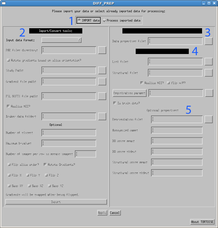
When the DIFF_PREP gui is first loaded, it defaults to the IMPORT data side (area 2 in the figure below).
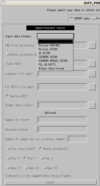
First, use the drop down menu to select your input image type. The options are currently Philips PAR/REC, Philips DICOM, GE DICOM, SIEMENS DICOM, SIEMENS MOSAIC DICOM, FSL 4D NIFTI and Bruker, as shown in the figure below. Each of the options will be described separately.
Philips PAR/REC
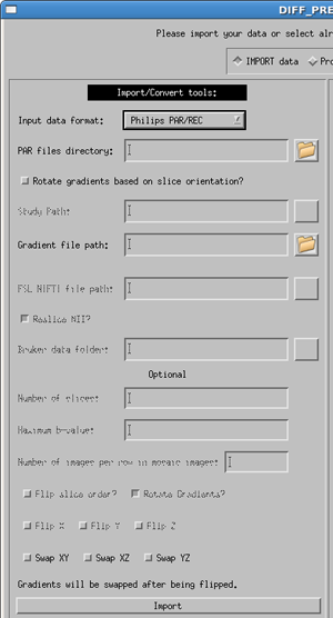
Enter the full path to the PAR file into the textbox, or use the button on the right of the box to browse for your PAR file. If your data is acquired such that the image reference frame and the gradient reference frame are not the same, turn on the option "Rotate gradients based on slice orientation?". This should be used in cases where the data was acquired with over plus.
For software versions 4.1 and greater, the gradients are specified in the PAR file. However, for earlier software versions you will need to supply a text file which contains 3 space or tab separated columns in the order of x y z with a row for each DWI volume acquired. If your data also contains a calculated trace weighted image (done by the scanner) please include an additional line of 0.0 0.0 0.0 to the bottom row of your gradient text file.
The user is given the option to swap the gradients. The gradient table is expecting the entries to be in the order or READ PHASE SLICE. If these are swapped, for instance if the phase encoding direction of axial images is changed to Left/Right instead of the standard Anterior/Posterior, this may be necessary. This should be a rare occurence.
Click the import button. This will create the proc directory parallel to your data directory. Inside there will now be a .list, .path and .bmtxt file as described above. It will also populate the List file field of the process side of the DIFF_PREP GUI.
Philips DICOM
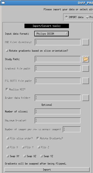
Enter the full path to the dicom image directory into the textbox, or use the button on the right of the box to browse. If your data is acquired such that the image reference frame and the gradient reference frame are not the same, turn on the option "Rotate gradients based on slice orientation?". This should be used in cases where the data was acquired with over plus.
Note: your DTI data must be in a single directory containing ONLY the DTI data (sub-directories for separate DTI series is okay, but all files in the same parent directory will be included in the import). Please separate your DTI series from other series (such as anatomical T1 or T2 images) before using the importing process.
The user is given two optional fields. First, the user scan specify the number of slices in a single brain volume. This should only be necessary in cases where this information is not available in the DICOM header, usually due to anonymization proceedures. Second, the user can swap the gradients. The gradient table is expecting the entries to be in the order or READ PHASE SLICE. If these are swapped, for instance if the phase encoding direction of axial images is changed to Left/Right instead of the standard Anterior/Posterior, this may be necessary. This should be a rare occurence.
Click the import button. This will create the proc directory parallel to your data directory. Inside there will now be a .list, .path and .bmtxt file as described above. It will also populate the List file field of the process side of the DIFF_PREP GUI.
GE DICOM/Siemens DICOM
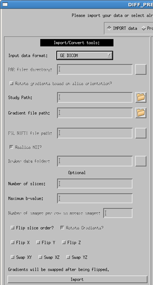
Select the correct manufacturer and data type for your data with the pull down menu. Usage for both dicom types is the same, as specified below, with a few minor differences.
Enter the full path to the dicom image directory (or use the button to browse for your data directory). Note: your DTI data must be in a single directory containing ONLY the DTI data. Please separate your DTI series from other series (such as anatomical T1 or T2 images) before using the importing process.
The gradient file is a text file where the first line contains only the number of volumes in your data, and the subsequent lines contain three columns in the order of x y z, with one line per volume in your data. Note: If you have multiple b-values the gradient vectors must be scaled to the b-value. More details are provided in the Quick Start Guide.
Optional information to provide the software are:
- Number of slices - The number of slices in a volume is not required but will speed up the import process if it is provided.
- b-value - this is the maximum b-value of your data. If not provided, the software will find the b-value from the DICOM header. However, due to changes in the DICOM header over time, it is sometimes possible that the software will be unable to locate this value, or will locate an incorrect. If the software cannot locate a value, an error message will appear in the status report window. Due to the possibility of inconsistencies in the dicom header files, we highly recommend that the user provide the maximum b-value. If not, please check that your b-matrix is correct. Occasionally we have seen a b-matrix of all zeros due to a zero b-value being identified in the dicom header.
- Flip slice order? - The tensor reference frame in DIFF_CALC assumes your data is acquired in the standard bottom-to-top (IS) fashion. If your data is acquired top-to-bottom (SI) please select this option in order to have correct directional information in your fitted tensor.
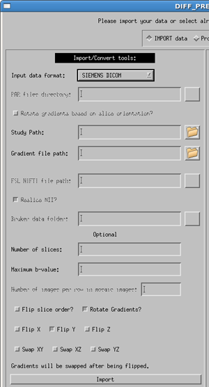
- Rotate Gradients? - SIEMENS ONLY - Siemens always applies diffusion gradients with respect to the magnet coordinate frame. This means that if images are acquired obliquely (i.e. the user rotates the field of view on the scanner console), this rotation is not taken into account in the gradient table provided to the scanner. Rotate Gradients is turned on by default, as it is harmless if your data is acquired in axial orientation, and necessary if your data are acquired obliquely. NOTE: the b-matrix which is computed and stored in the DICOM header for Siemens does take this rotation into account. However, TORTOISE requires a gradient table as input, so the b-matrix from the DICOM header is not used at this time.
- Flip X, Flip Y, Flip Z - If the directions of your gradient file are inconsistent with the reference from of our software, it may be necessary to use these buttons. Note: In our experience, the convention from Siemens is different than our convention, and requires the use of the Flip Y option, therefore, for both Siemens dicom and Siemens Mosaic dicom files this is the default used.
- Swap XY, Swap XZ, Swap YZ - The gradient table is expecting the entries to be in the order or READ PHASE SLICE. If these are swapped, for instance if the phase encoding direction of axial images is changed to Left/Right instead of the standard Anterior/Posterior, this may be necessary. This should be a rare occurence.
Click the import button. This will create the proc directory parallel to your data directory. Inside there will now be a .list, .path and .bmtxt file as described above. It will also populate the List file field of the process side of the DIFF_PREP GUI.
Siemens Mosaic DICOM
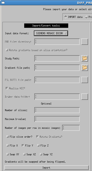
Using the Siemens Mosaic Dicom import tool is identical to the GE and SIEMENS DICOM formats as described above. However, there are a few differences internally to the code of which the user should be aware.
This data format contains all of the slices for one DTI volume in a single 2D mosaic view. Therefore, to be read by our data, we must cut apart the images into standard slice-by-slice data. This new data is saved as floating point slices in a new directory. Thus, the naming convention becomes: original data: my_data/, raw floating point data: my_data_slices/, imported data: my_data_proc/.
Additionally, this process can take up to 5-10 minutes, depending on your computer and on the size of your data set.
In TORTOISE V1.3.0, Rotate Gradients? is by default turned on. The user does not currently have the option to turn it off. This option SHOULD be used at all times, but if the user requires it to be turned off, they should contact us at tortoisedti@gmail.com for a slightly different version of the software.
FSL 4D NIfTI
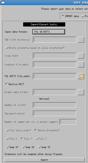
For 4D NIfTI data, the software is expecting the data structure and naming convention of FSL. Mainly there needs to be a 4D NIfTI data file containing all of your diffusion and non-diffusion (b0) weighted images, as well as a corresponding bvectors and bvalues files, named exactly bvecs and bvals. This can be created using the dcm2nii tool available through MRICron.
Due to inconsitencies in the way nifti files are created by different software packages, the user is given the option to either use or not use the transformation matrix in the NIfTI header. This is controlled with the Reslice NII? option. By default it is turned on, and in most cases this is desirable. However, if you view your raw DWI images in DIFF_CALC and find that they are oriented in an unusual, or un-desirable way, please re-import your data with Reslice NII turned off.
An additional option is to Swap XY, Swap XZ, or Swap YZ. The gradient table is expecting the entries to be in the order or READ PHASE SLICE. If these are swapped, for instance if the phase encoding direction of axial images is changed to Left/Right instead of the standard Anterior/Posterior, this may be necessary. This should be a rare occurence.
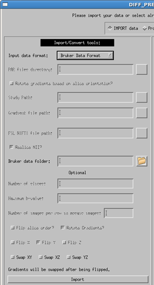
Bruker Data Format
This import routine should be considered Beta, as we have had limited access to Bruker data for testing. Please contact us at tortoisedti@gmail.com if you encounter difficulties. This will help us to make this routine more robust.
Enter the full path to the bruker raw data directory (or use the button to browse for your data directory). All diffusion data contained within this directory will be included in the importing. If you have multiple DTI acquisitions which you do not want to be combined, or which have different acquisition parameters, they should be separated into different data directories.
The users is given the option to Swap XY, Swap XZ, or Swap YZ. The coordinate system of Burker data is complex, and while all efforts are made to correctly interpret the gradient information, we give the user the option to swap gradient directions in the case that the import is not correct.
